DIY Bench Tools
When I first started my projects, I didn’t have a lot of tools on hand or a decent amount of practice using tools that are common in DIY scenarios. Also, at around this time, many of my projects called for testing components on a breadboard, crimping, and soldering. To help improve and practice using some of these tools, I thought it would be a great project to create some tools that I can incorporate when designing and planning new projects.
The DIY Tools
Fume Extractor
After the electronics are tested and I’m satisfied with the components and wiring schematic, I move the components from the breadboard and start to integrate them into the project I’m working on. In earlier projects I relied heavily on soldering these connections. Although, to improve reliability and quick repair/troubleshooting, many of my recent projects incorporate crimped connections. In both cases I still rely on soldering to some extent. To avoid inhaling the fumes that come from the melted rosin, I found a CAD design on instructables for the fume extractor frame and fan shroud.
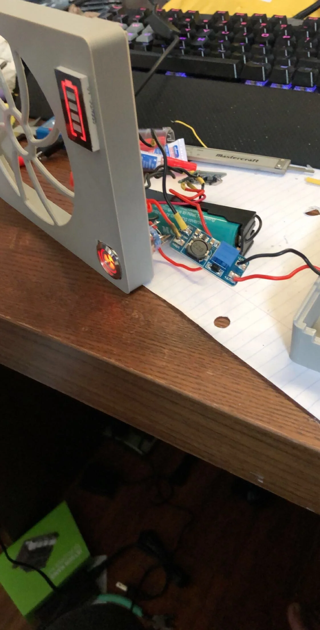
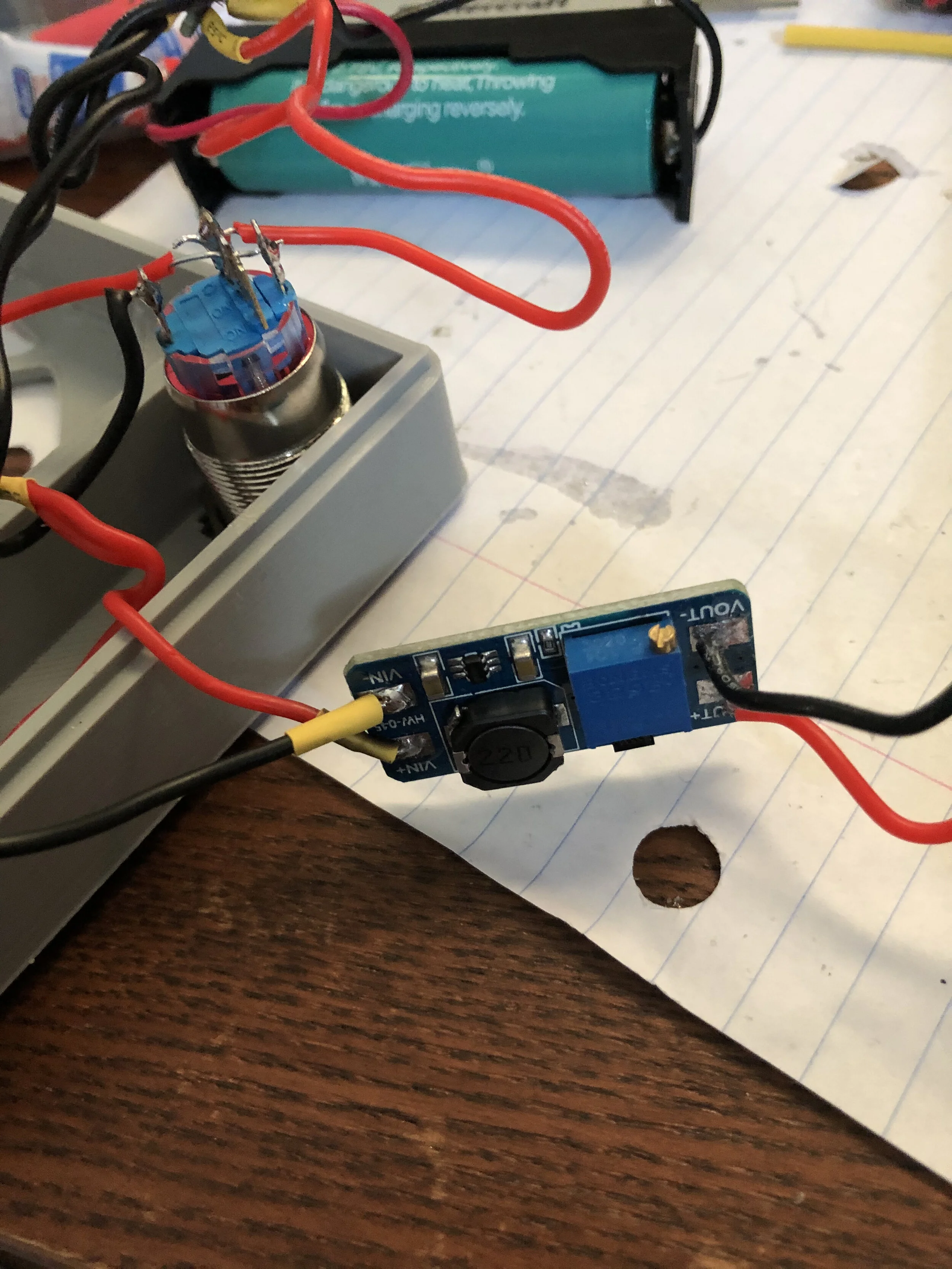
After a few modifications to the design to include certain components I wanted in the tool, I’m able to solder safely and more efficiently without the fumes interrupting my workflow. The main components in the fume extractor is a 120mm CPU fan powered by an 18650 battery. A DC step-up converter is used to power the 12V fan.
DC Power Supply
Initially, when testing components or if I needed a DC source for a project I was working on the breadboard, I would elect to use batteries. For small projects, this wasn’t usually a big deal until I started working with bigger devices. However, when working with electric motors or linear actuators, these devices usually called for a DC voltage of 12V - 24V. On a tight budget, I elected to create my own bench top DC power supply.
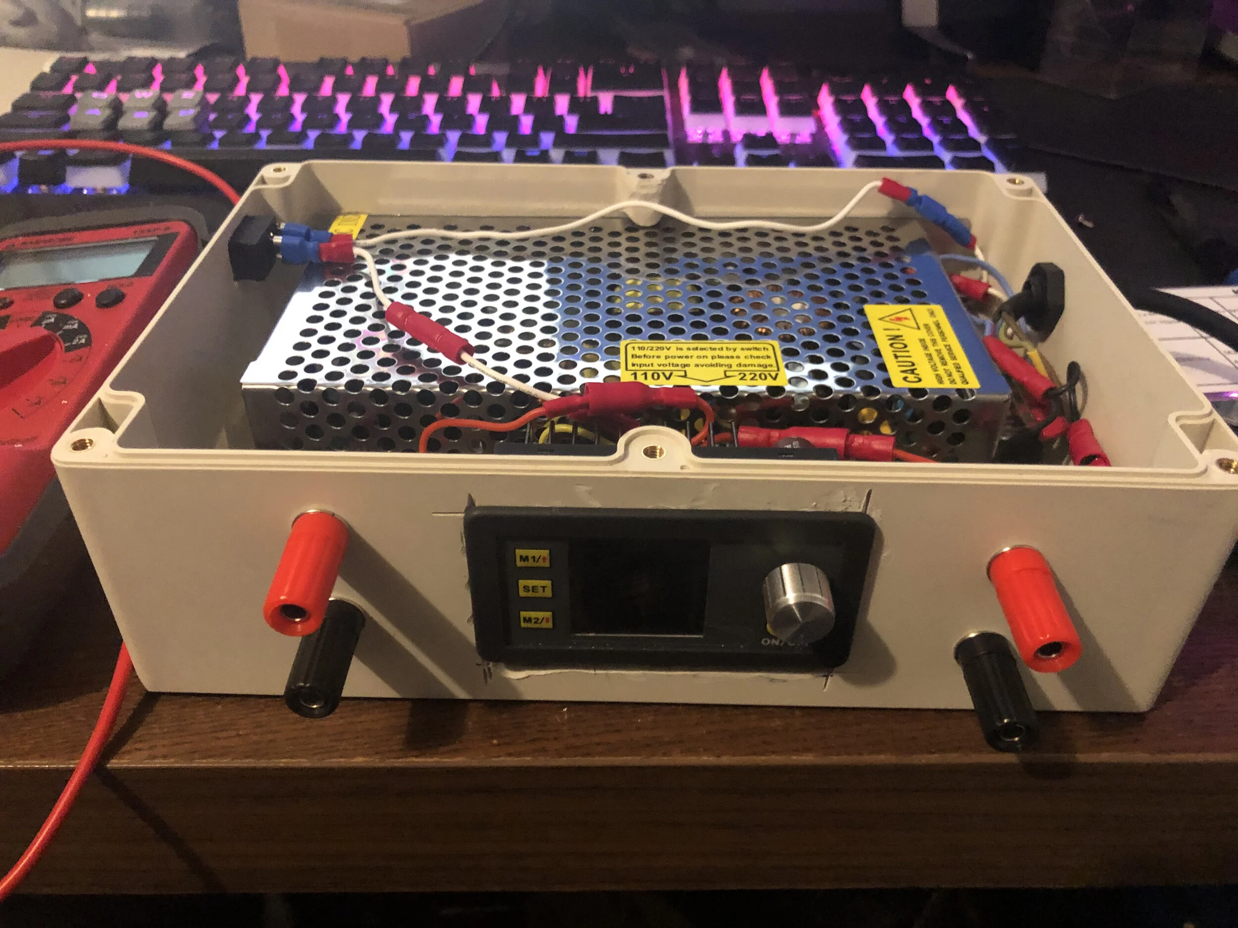
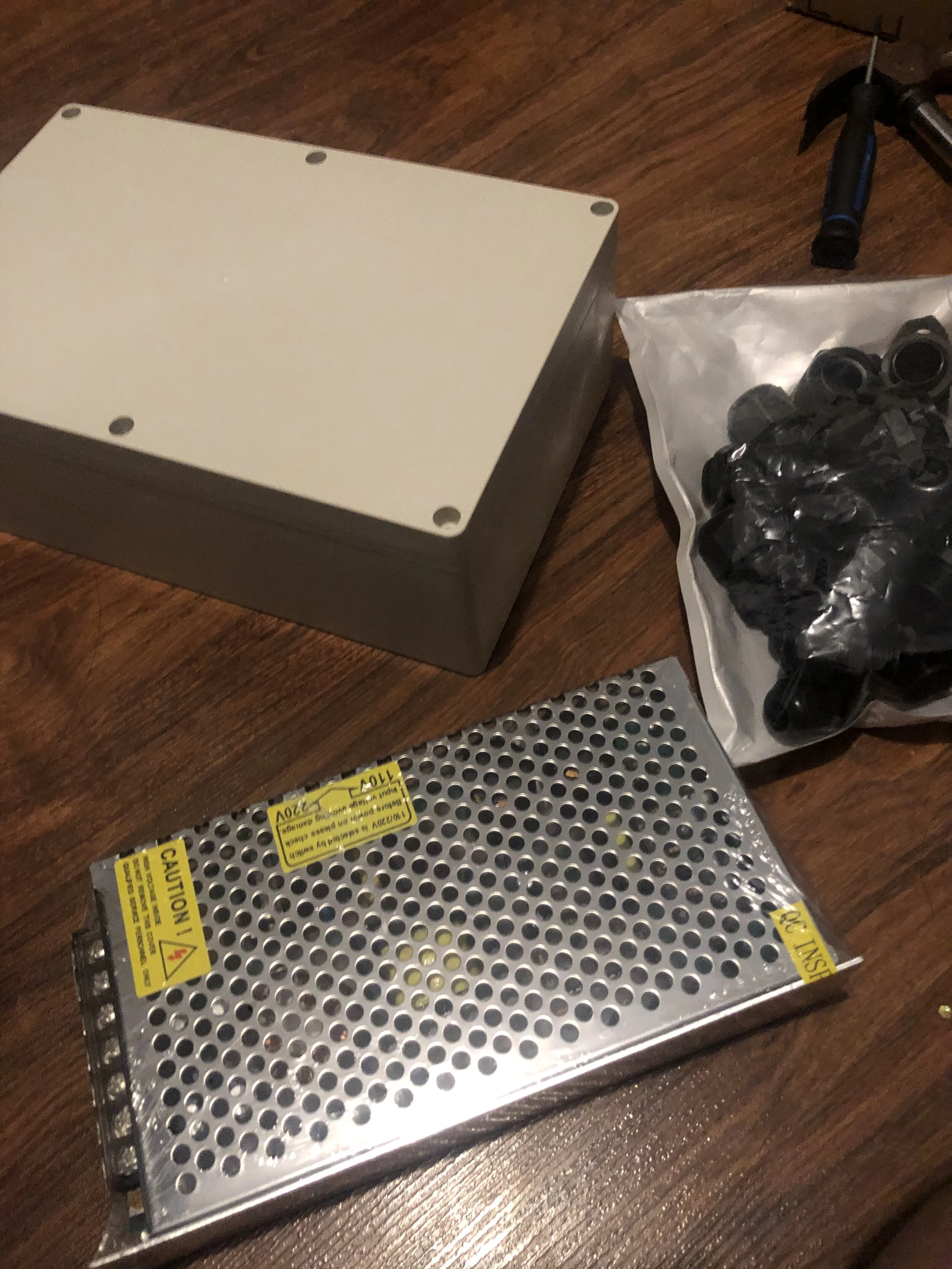
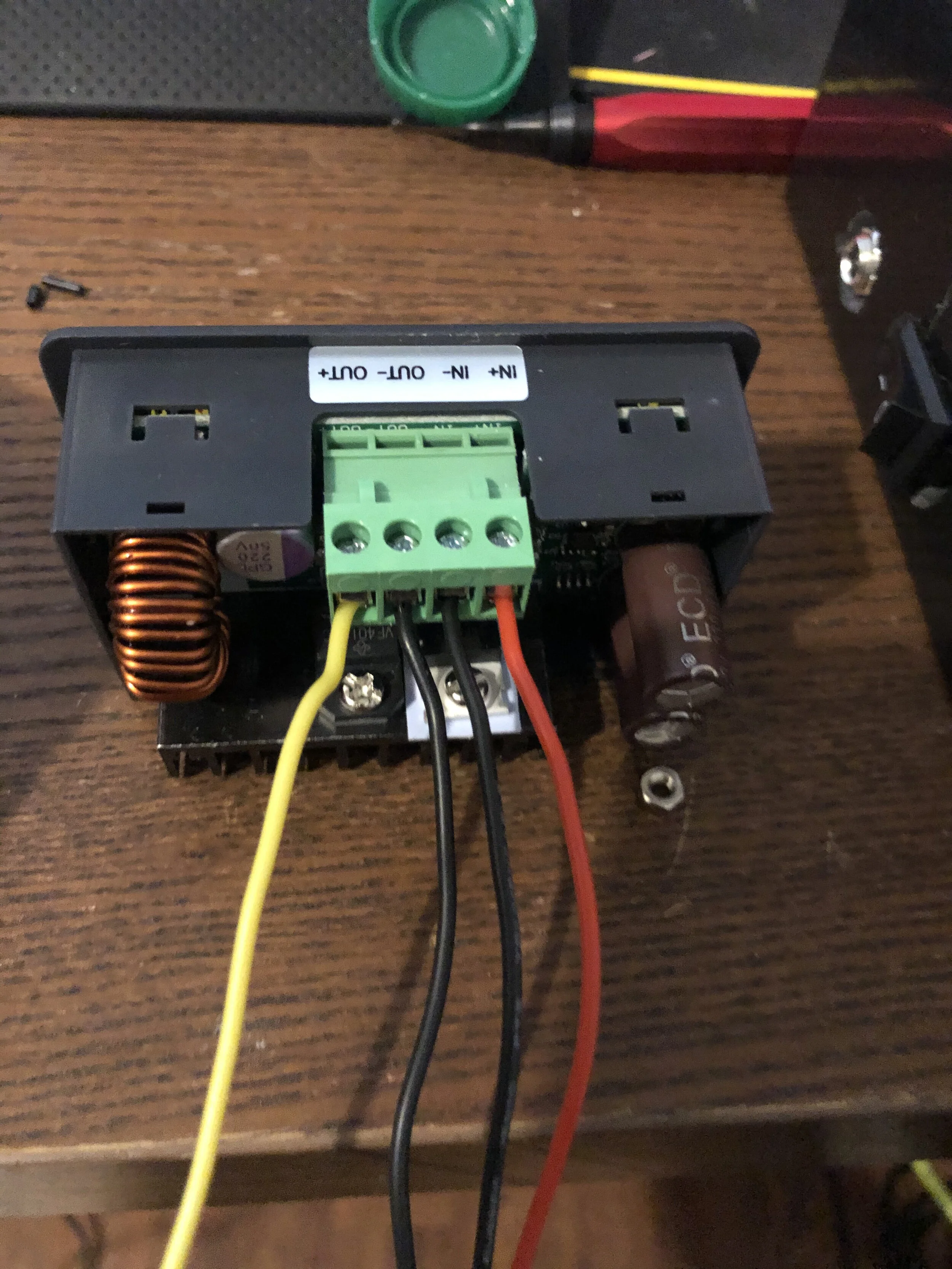
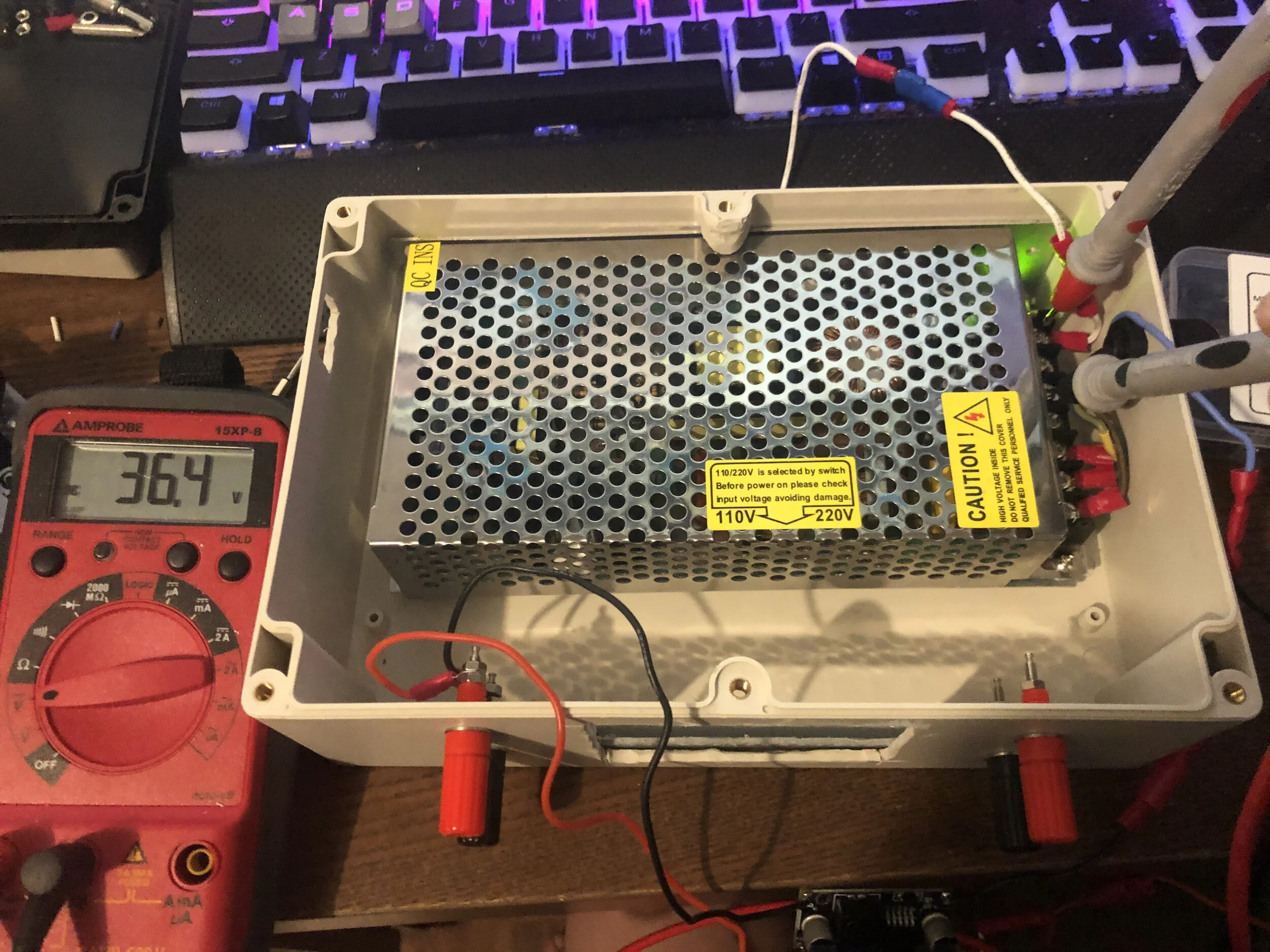
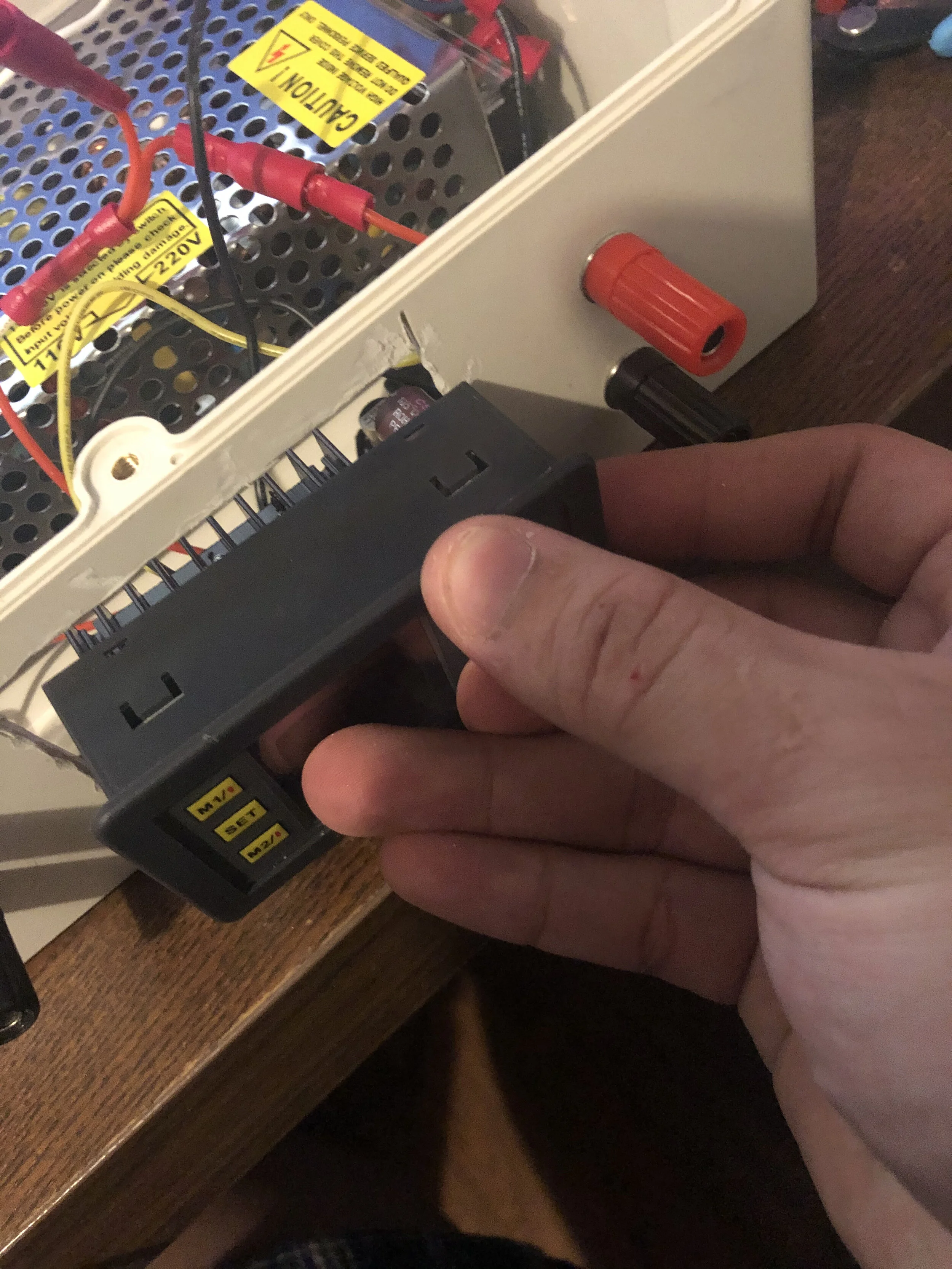
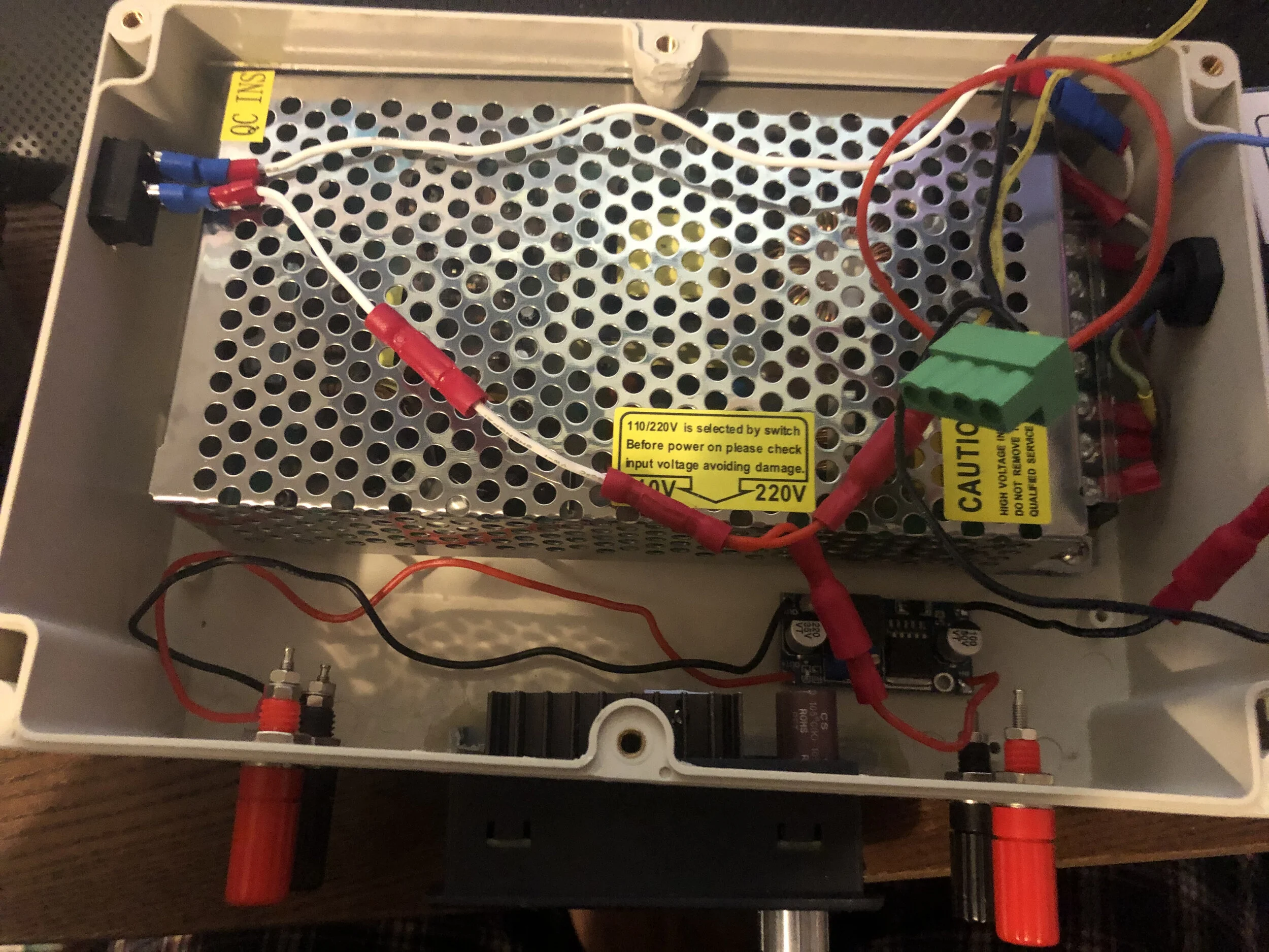
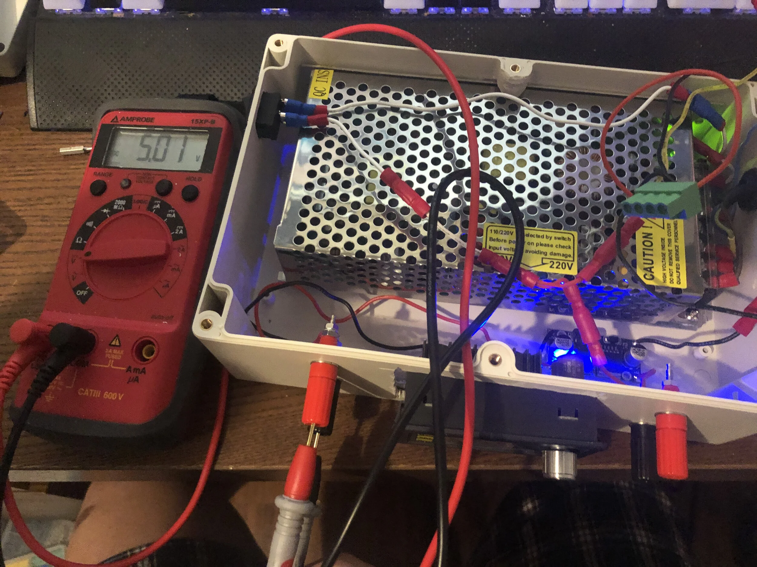
This DC power supply uses a rectifier I bought on amazon that is capable of an output voltage of 36V and an output current of 5A. The voltage regulator attached to the middle of the plastic enclosure allows the user to step-up or step-down the DC voltage coming from the power supply. The left terminals seen in the picture is attached to the same power supply but with it’s own separate buck converter to output a constant DC voltage of 5V. These terminals were properly labeled after assembly to ensure that there was no confusion to which output was 5V or the variable DC voltage.


